SkySensor2000 Internal Battery Replacement
Replacement Procedure For A Failing Internal Battery
John D. UptonDecember 7, 2016
If you own and still use a Vixen SkySensor2000 PC mount control box for the Great Polaris and other GEM mounts, you may have noticed that it no longer holds correct time and the defaults for your location are also missing each time you power up. The SkySensor2000 PC uses an internal battery to power its real time clock and hold your location defaults. After 15 to 20 years, these batteries are finally failing. The battery was not meant to be user replaceable but with care, the owner can follow this procedure to bring the unit back to full functionality.
The SkySensor2000 contains a long-life battery which is used to maintain internal memory parameters between powered usages. The battery is not meant to be user replaceable and is soldered permanently onto one of the internal circuit boards inside the SkySensor2000 hand control box. The user is urged to have the hand control box serviced by the manufacturer should the battery ever need to be replaced. Since these units are now approaching more than 15 years of age, their batteries may be reaching end of life and obtaining service on an old discontinued product may be problematic for many owners.
This internal battery is a non-rechargeable 3.6 volt 2000mAh AA-size-class Lithium-Thionyl-Chloride type. The OEM (Original Equipment Manufacturer) battery is of type Toshiba ER6V. There are few sources for this battery type number outside of Asia. Luckily, there are a number of replacement part numbers available for the battery but many differ in attachment style. There are at least three styles of this battery being sold today. One looks like a normal AA size battery with a button-type positive terminal. The battery is a also available with wire leads and connector as well as a style with short solder tabs welded to the battery terminals. The replacement battery for the SkySensor2000 must be of the style with solder tabs to ensure a relatively easy replacement. Battery sizes in the LS14500 series can be found in the AA-size-class solder-tab style required for the SkySensor2000. Any replacement must be of the same voltage and physical size specifications as the OEM Toshiba ER6V. For the replacement pictured here, an Interstate Batteries type LIT2065 was used.
Anyone with experience in working on electronic circuits and soldering small sensitive components should have the skills to make the replacement themselves. This guide should help walk the technician through the process. The tools required for this task include a Phillips screwdriver, diagonal cutter, tweezers, small file (which may not be needed), solder sucker and/or braided solder wick, an ESD-controlled soldering pencil, flux-core electrical solder, and an ESD work mat. (ESD is an electro-static-discharge -- the soldering unit must be of the grounded type that will protect the low voltage static sensitive electronics of the SkySensor2000. In addition, the whole disassembly operation should be performed on a table or workbench which has an ESD conductive surface mat.)
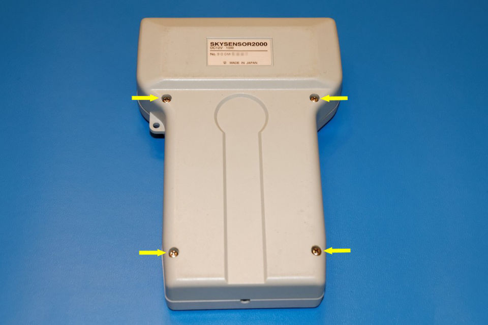
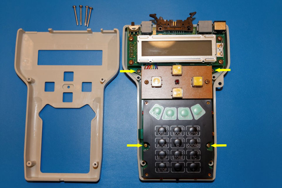
Figure 1 shows the first step in the disassembly process. Locate and remove the four screws on the back of the SkySensor2000 hand control unit. All four will be of the same length. Set them aside and turn the unit face up. The face of the hand control box should lift off revealing the front of the electronics card assembly. There are five cards which make up the whole assembly. The three top-most cards are located on approximately the same plane. They are the LCD display card, the push-button card, and the membrane-type numeric function pad card. Two additional electronic cards are stacked below this top-most layer of cards.
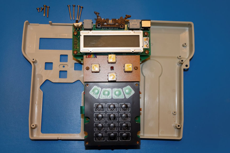
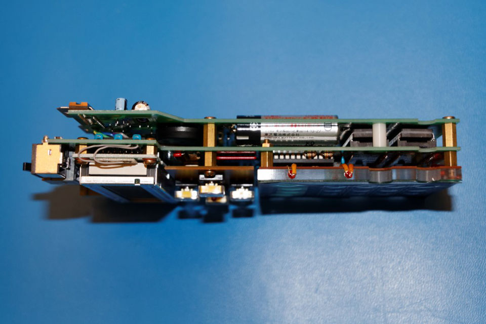
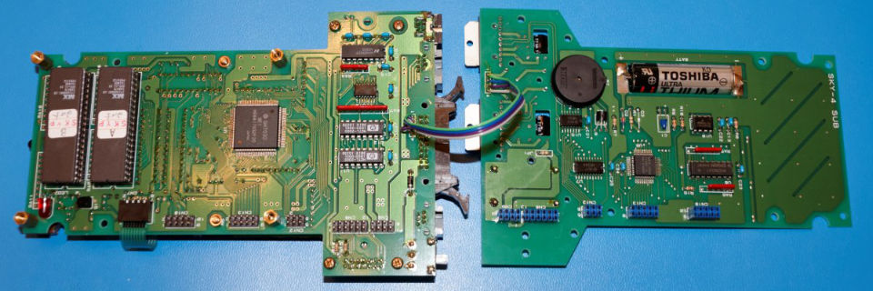
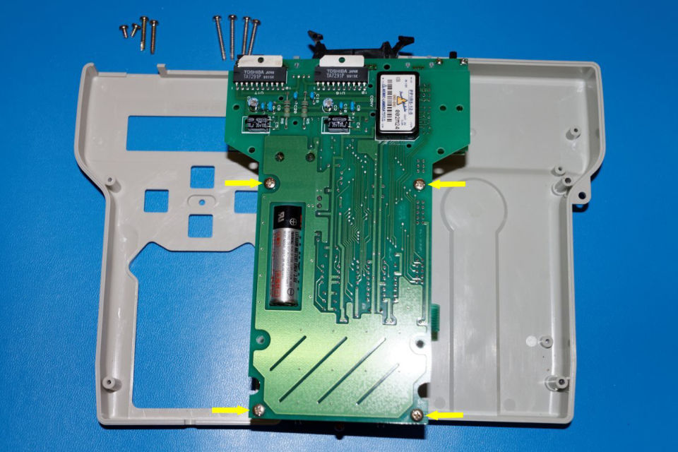
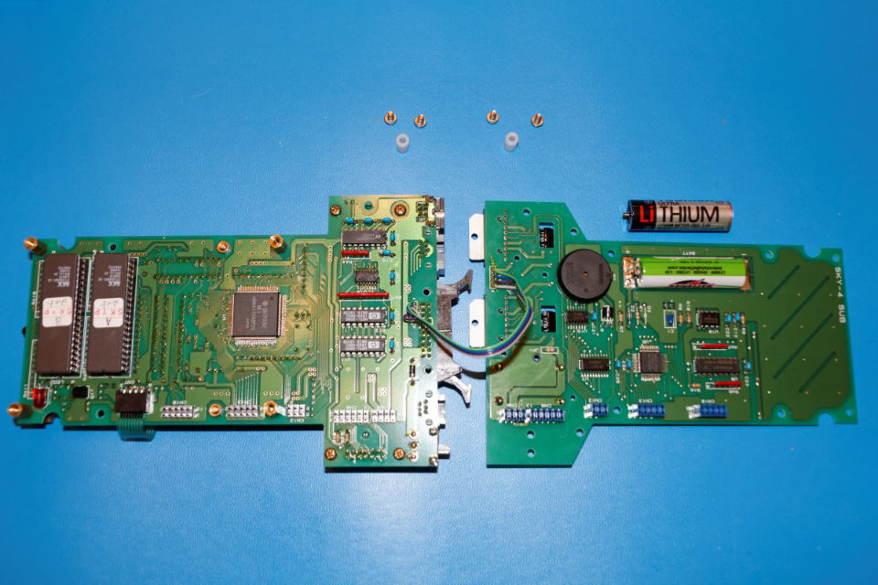
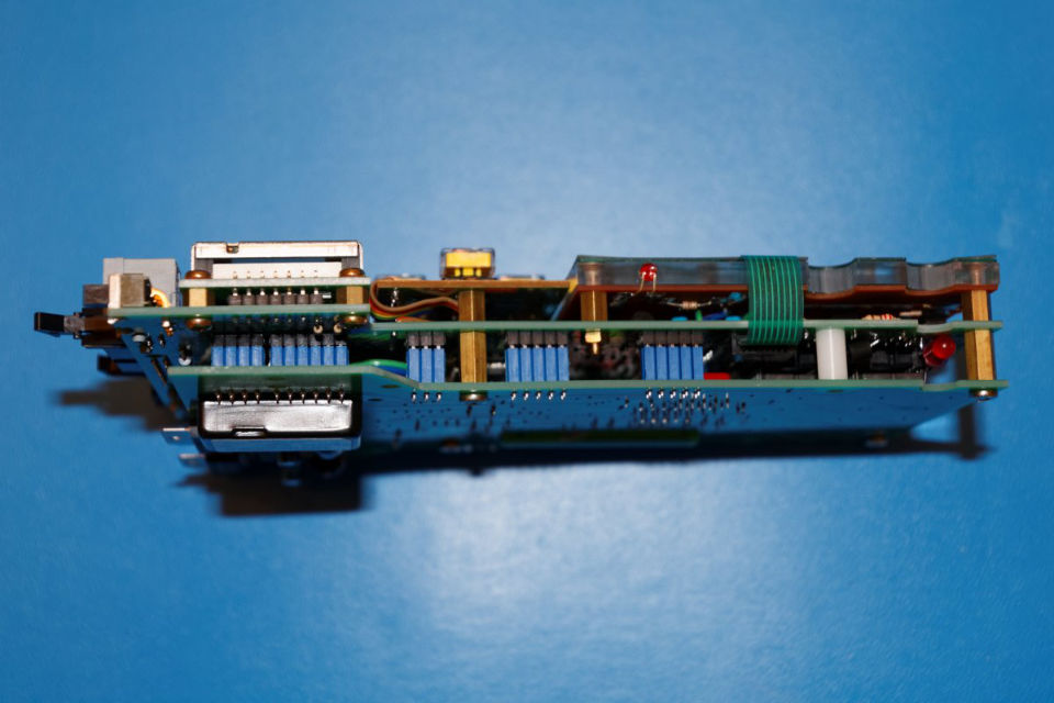
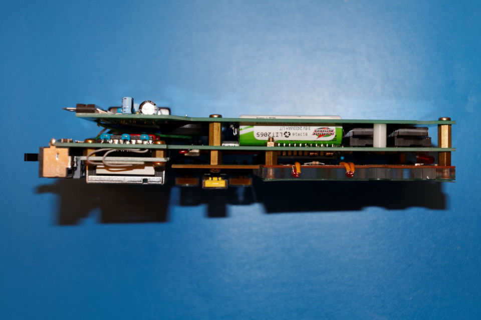
The next step in disassembly is to remove the electronics card stack from the bottom portion of the case. It is held in place with four screws shown in Figure 2. The two upper-most of the marked screws are short while the bottom-most two screws are longer. Once these screws are removed and set aside, the electronics card stack may be removed completely from the case as shown in Figure 3. Once the stack is removed, the two lower cards may be seen more clearly. The electronic cards in the stack are separated with metal standoffs which also serve to hold the assembly together. Figure 4 shows the layered stack of cards from a side view. The battery to be replaced is also seen in this view.

Now the bottom card has to be removed from the stack to gain access to the solder tabs on the battery. This is accomplished by removing the four screws on the back of the card assembly as marked in Figure 5. Note that when the bottom card is removed, there are two non-secured nylon stand-offs that will likely fall out. (It is also possible that these will fall out when the card stack is first removed from the case as the bottom two screws pass through them. Once the bottom screws holding the assembly in the case are removed, these two nylon stand-offs are freed.) Make note of the original position of the these components as shown in Figure 6 -- one on each side of the card stack assembly. (These nylon stand-offs line up with the two holes for the lower screws that attach the electronics assembly to the back case half. Refer back to Figure 2 where the screws were shown.)

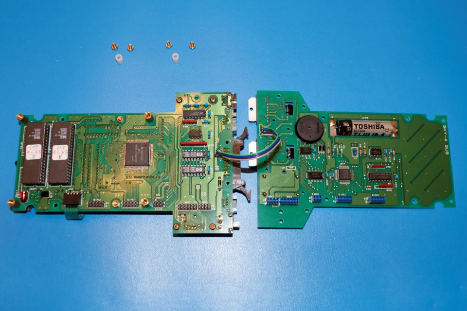
With the four screws on the back of the electronics card stack removed, the back card can be separated from the stack. The only thing holding it in place at this point are the connectors between the two bottom cards and a non-removable cable between those same cards. The connectors can be seen in Figure 7 as stacks of blue and black connections between cards. Very carefully work the two cards apart by prying slightly at each connector location. Be careful not to pry the cards apart in an uneven manner. Work each connector group a few hundredths of an inch at a time until the cards separate. Once the connectors disengage, the four wire cable will be seen between the two cards. Leave this cable (soldered on both ends) in place and simply open the cards like the pages of a book. The cards will then be able to lay flat on the work surface as shown in Figure 8.
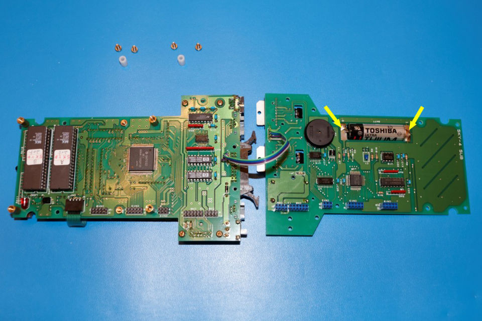
Next it is time to remove the old battery. Before doing so, it is a good idea to measure the voltage to make sure the battery is indeed bad. The voltage of a new battery will measure just above 3.6 volts. On the unit pictured here, the old battery measured only 0.05 volts -- it was truly and completely exhausted after fifteen plus years of service. To remove the old battery, it is best to cut the short solder tabs between the battery and the circuit board at the points indicated in Figure 9 below. A pair of electronics diagonal cutters makes this a simple process. After cutting the tabs, gently coax the battery out of the slot in the circuit board. It may be a tight fit.
The solder tabs on the circuit board should now the cleaned up before installing the new battery. Using tweezers, hold onto the short section of old solder tab on the card where the excised battery resided and use the soldering pen to melt the solder. The old tab will release. Repeat this process for both the positve and negative solder tabs on the card. This may still leave a sizable blob of old solder on the tabs. Any raised solder mounds can be removed with a solder sucker or braided solder wick. Once the tabs are clean, the new battery can be fit into position.
Warning: Be very sure to place the new battery into the slot with the correct polarity as marked on the circuit board even when only testing for fit. You can also use the old battery as a guide to orientation prior to its removal. This is extremely important because the solder tabs on the new battery can contact the circuit board pads and apply power to the SkySensor2000's memory components while trial fitting the new battery. Even a very brief reverse polarity connection of the battery to the card contacts can permanently damage the memory components on the circuit board.
In some cases, the new battery may be very slightly longer than the OEM battery. This was the case with the LS14500 style battery used in this particular replacement. There is only about 0.015" of spare space for the OEM Toshiba-branded battery. The replacement battery was about 0.018" longer than the original. To solve this, a tiny file was used to shave a few thousandths of an inch out of the negative end of the slot in the circuit card (If this is required, always remove material from the negative side of the slot since the circuit card's ground plane surrounds the slot on both top and bottom of the card while the positive plane is present on the top side near the positive battery terminal. If the length of the slot is enlarged from the positive side, some power to ground short circuits could be created when soldering due to the proximity of the positive and negative copper patterns on the circuit card. Shorting a lithium battery in such a manner can generate large electrical currents and cause the battery to burst or catch fire.)
Before soldering the new battery into place, bend the solder tabs so that they can lie flat against the corresponding tabs on the circuit card. Some excess length will need to be trimmed from the battery's solder tabs so they do not overhang the contact areas on the circuit card. With solder tabs bent and trimmed, place the new battery into the slot and solder it into place. Be careful to apply just enough heat to cause flowing of the solder into the connections but not so much so as to overheat the circuit card or battery. Verify that the solder joints look clean and secure.
Now is a good time to check the battery installation. Measure the voltage present between the positive and negative tabs on the circuit card. It should be something just over 3.6 volts. Be sure to measure the voltage on the circuit card so that the continuity of the soldered connection is tested rather than just the battery voltage at its terminals. With the new battery installed and checked, the remaining steps are to begin reassembly.
Close the "pages of the circuit board book" and carefully align all the connectors along the left side of the electronics card stack assembly. Gently push the connectors together evenly ensuring that all pins and sockets are properly aligned. It is best to work up and down the connector row repeatedly until each connector and pin are fully seated and the back-most circuit card in in contact with the metal stand-offs. At that point, reinstall the four short screws which were removed as shown in Figure 5 above. Slip the two nylon stand-offs back into position between the two bottom cards of the electronics card stack. With the screws replaced, the electronics card stack should now look like Figures 11 and 12.
Replacement of the circuit card stack into the case may now be done. Drop the stack into the rear portion of the case and secure with the four screws shown in Figure 2 before. Remember that the two top screws are much shorter than the bottom two. When inserting the bottom two screws, make sure that the screws pass through the nylon stand-offs between the two rear-most cards of the electronics card stack. You may need to move the nylon stand-offs around a bit as you insert the screws to make sure they are aligned properly.
The final step in reassembly is to place the front cover onto the SkySensor2000, turn the unit over, and secure with the four screws through the back of the unit as shown in Figure 1 above. The reassembled unit may now be tested for functionality.
Testing the repair is very straightforward. All you need to do to test the repair is to connect the unit to your mount, apply power, and turn the SkySensor2000 on. You will see a quick message flash across the screen about initializing the internal memory. Go through the initialization process entering your time, date, and location information. Next, shut the unit down, disconnect it from power, reconnect, and turn it back on. If all of your initialized data is still correct, then the repair was a success.