Modular Optical Tester Design
Use Simple Interchangeable Test Head Adapters For Multiple Tests
John D. UptonJan 15, 2003
Mirror making and optical fabrication can become quite addictive to many telescope makers. After finishing their first mirror, some ATMs go on to make more telescopes of greater complexity. In addition, ATMs want to improve the quality and performance of their subsequent optics. Many will resort to using different or additional testing procedures. Presented here is a versatile, modular design for a tester optimized for performing the Ronchi Test, Foucault Test, Wire Test, and Ross Null Test.
Over the thirty plus years I have been interested in amateur telescope making, I have built, modified, and rebuilt my testers over a half dozen times. I have always planned to make one last perfect tester. The trouble is that I have changed my testing methods almost as many times as I rebuilt my testers over the years. Just when I think I know how to optimize my tester, I change testing methods and start all over again. Such is the fate of a unreformed telescope nut.
This past summer, I needed to throw together a quick and dirty Ronchi tester. In looking through all my various junk parts boxes, I was able to piece together a design that was cheap and quite capable. Liking the results, I began to design a tester around the first rough prototype I had built. What I ended up with is a tester that is easy to modify for several different types of testing. Rather than actually do the modifications, however, I decided to just make several nearly identical subassemblies that could be turned into a very versatile multi-use tester system. This article describes what I have come up with. Hopefully, there will be enough detailed information here for you to duplicate this tester design should you desire to do so. Figure 1 shows the second prototype I built to improve on the basic design.
Overall Design Requirements
A number of things have always bothered me about my previous testers. Based on years of use, I had particular hard requirements in mind for what I viewed as the ultimate amateur tester. Here are some of the requirements I decided to incorporate in my new tester design.
- Moving Source Design
- Over / Under Light Source Placement
- Low Power Solid State Light Source
- Easy Setup & Tester Alignment
- Provision For Ronchi Test Use
- Provision For Foucault Test Use
- Provision For Wire Test Use
- Provision For Dall Null Test or Ross Null Test Use
- Provision For Gaviola Caustic Test Use
- Provision For Adding a Web Camera
These requirements grew out of years of frustration with previous testers. For overall mechanical simplicity, I chose to use a moving source design. In this type of tester, the light source is mounted on the same carriage that carries the test observation point, be it knife edge, grating or whatever. This design type also lends itself to reducing the lateral separation between the source and observation point. This can be quite advantageous since it reduces the astigmatic effects in the various tests. I actually wanted to eliminate this lateral separation completely, opting for a source immediately over or under the observation point. This is the basis for the typical "slitless" Foucault tester design. While there are still some astigmatic effects with an over and under arrangement, their effect is oriented 90° to the tester's usual measurement direction for most tests and therefore may be more easily ignored.
My previous testers had been built more or less resembling the plans seen in many of the ATM texts that are widely available. One of my major complaints has been the use of relatively high power light sources in order to attain sufficient brightness. This traditionally meant extra heat being generated near the testing point with its attendant air turbulence and annoyance to the person doing the testing. It also usually means extra light shielding to keep the surplus light away from your eyes while testing. These were nuisances I wanted to avoid. I vowed to only use an LED or laser for my light source on all future testers. Surprisingly enough to many beginning ATMs, the extra brightness is not required by the most common tests; it is to make it easier to get the tester aligned with the optics under test. A small "normal" (15 to 50 mcd) brightness surface mount chip LED is more than bright enough to do testing under usual home lighting conditions. Many amateurs do not realize just how dim the source can be during testing without causing any problems.
Setup and alignment is a separate matter and has always been somewhat difficult for me. Often, it would take me three times longer to align the tester than to run a test. I was determined that my new tester would incorporate a method for quick, accurate alignment. Since both lasers and super bright LEDs are both readily available and inexpensive these days here in the United States, I decided to add a means for easy bright light alignment to the basic tester design. Last year I purchased some very small laser pointers from Harbor Freight Tools for less than five dollars (US) each. These are perfect for this use. My first junk parts prototype used one of these lasers for alignment. I also discovered that LEDs with a brightness greater than 2000 mcd are usually sufficient for alignment. While my initial prototype used a laser for alignment, the second prototype uses a super-bright LED. The basic design presented here follows the second prototype and uses a bright LED source to aid alignment.
In order to make the tester easy to use for a variety of tests, I adopted a design which allowed interchangeable "carrier fixtures" or adapters personalized to the type of testing being done. Individual adapters can carry a Ronchi grating, a Foucault knife edge, or a slit and wire for performing different tests. Switching from one test to another is as simple as removing the current adapter and replacing with another. The adapters are made of metal and are magnetically held in place on the test head.
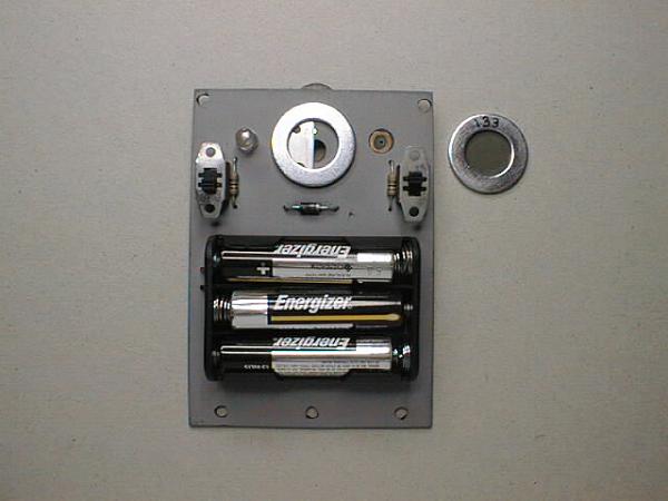
Finally, the design was made to be self powered. Provision was made to mount a battery holder directly on the tester head. While this compromised compactness somewhat, the convenience was well worth it. I chose to use three 1.5 volt "AAA" sized batteries. With the low power consumption of the LEDs involved, the tester will run for well over 30 hours on a set of batteries. A much more compact design is possible by using smaller batteries such as A76 or LR44 size. Though this reduces operational time, the substantial size reduction may prove useful to some.
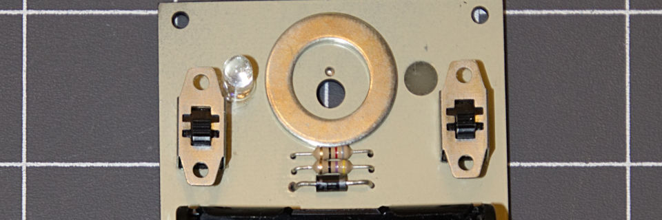
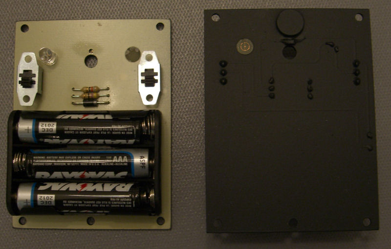
A key aspect of this tester design is that it is built directly onto a printed circuit board to ease construction. All the components of the tester head mount directly to the circuit board. The whole assembly is roughly the size of a credit card and about 1/2 inch thick. The battery holder occupies most of the space on the assembly. Two switches control the LEDs. The switch on the right side is the master power switch. In the ON position, the small chip LED is always powered. The switch on the left is the alignment switch. It controls power to the super-bright LED. Two current limiting resistors for the LEDs and a diode complete the assembly.
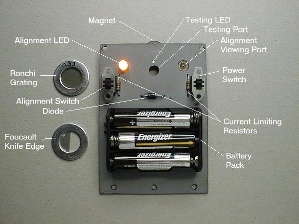
As can be seen in Figure 2 at the right the tiny surface mount chip LED is mounted on the reverse side of the printed circuit card over a very small (0.040 inch) diameter hole. Immediately below the LED is the viewing hole through which the testing is conducted. These two holes may be placed such that they nearly meet. This arrangement allows for zero lateral offset in the test and a vertical offset only slightly more than the radius of the viewing port hole. Astigmatism from the tester is very nearly eliminated with this design.
A small powerful magnet is glued to the back of the assembly immediately above the chip LED. This magnet provides the holding force for attaching the interchangeable optical test element carriers such as a Ronchi grating or Foucault knife edge. The test elements are epoxied into place on a steel washer. Separate washers carry gratings, knife edges, or slits and wires for performing different types of optical tests.
Tester Construction
Construction of the tester assembly begins with the printed circuit board. You may use any of several methods to make this circuit board. You can hand draw the component pads and wires onto a raw board or use the circuit design patterns available below to "print" the supplied design onto the board using standard PCB photo-etching construction techniques. For a board this simple, hand drawn patterns are much easier to make and are perfectly acceptable.
When making simple circuit boards like this, I use the following method. I print out the board pattern actual size on my printer. (Be sure to measure the resulting printout in both X and Y dimensions to ensure that the printer didn't scale the printout by any appreciable amount.) Next, cut the raw copper-clad circuit board so that it is about 1/8 inch larger in each dimension than the desired finished board. Securely tape the printout to the copper side of the board and make sure that it fits without overhanging the edges of the raw board. Pay close attention to whether the printed circuit pattern was reversed or not.
Now, use a center punch, prick punch, or sharp nail or brad to mark the positions of all the holes in the board. With a sharp punch, only a relatively light tap with a small hammer or mallet is required to slightly dent the card at the proper point. Center punching the holes, as it is called, greatly improves the location accuracy of the resulting drilled holes. Take care in centering each of the punch marks in the printout for each hole. The positions must be accurate or you will likely have trouble mounting the components later.
After all the holes are center punched, you may remove the printout from the raw circuit board. The next step is to drill all the holes in the board. You may refer to the drill list supplied with the circuit pattern or adopt a standard size for each type of hole. Most small electronic components will fit well in a 0.030 inch diameter hole. Special components, such as the slide switches used in this design, may require slightly larger holes. Since the holes' positions have been punch marked in the copper, you may use a hand held drill to make the holes. A high speed drill, like a Drimmel Tool, works best for very small holes such as these. The larger holes are best done on a drill press but it is not required; just be very careful not to let the holes "wander" as they are drilled.
Once all the holes are drilled, you should thoroughly clean the copper cladding on the raw board. A household copper cleaner may be used to good effect. (Do not use the type that is meant to leave a film on the copper to ward off further corrosion.) Rinse the board carefully and take precautions not to touch the cleaned copper surface. To mark the wires and component solder pads on the copper, use an "etch resist" pen. An ordinary Sharpie® indelible marker works fine for this use. Draw the connecting wires of the circuits onto the board and check them carefully for thin areas or gaps. The resist ink must completely cover the copper areas you do not wish to be etched away. On a simple circuit such as this, it helps to make the wires fairly wide. A width of 0.050" to 0.100" will work well. After drawing in the wiring connections, draw a solder pad around each hole for the component leads. You may simply draw a small ring around the drilled hole. If you have a second Sharpie marker whose tip is getting a bit worn, you can also just push the marker firmly into the small hole and spin it in place. It will flair out slightly and make a nice concentric ring of ink around the edge of the hole. After a little practice, you will find that you can make very nice component pads this way.
Now it is time to etch the raw card. I prefer to use ammonium persulphate as the etching solution. I like to use ammonium persulphate as it is cleaner and easier to work with than ferric chloride. It also has the advantage of coming in solid crystalline form which can be dissolved in water as needed. (Do not mix more solution than you need as it has a limited shelf life.) I mix the ammonium persulphate in a ratio of about 35 grams per 200 milliliters of water. This amount is enough solution to etch approximately twenty five square inches of copper clad circuit board. Make up just enough solution for your current use. You should use very warm water when you mix the solution as this aids in the etching process considerably. Pour the etching solution into a non-metallic container just large enough to hold the board to be etched.
Place the raw board into the etching solution copper side up. Gently rock the container slightly as the etching takes place. Complete etching of the exposed copper will take approximately 15 minutes to an hour depending on temperature, the strength of the etching solution, and the thickness of copper cladding on the raw board. As the etching solution is exhausted it slowly begins to turn blue. Once all traces of exposed copper have been etched away, remove the card from the solution and rinse in running water. If any small areas of copper are found to remain, place the card back into the etching solution. Take care not to over-etch the card since the copper making up the wires may be undercut.
Paragraph - Vestibulum ante ipsum primis in faucibus orci luctus et ultrices posuere cubilia Curae. Suspendisse vel placerat ligula. Vivamus ac sem lac. Ut vehicula rhoncus elementum. Etiam quis tristique lectus. Aliquam in arcu eget velit pulvinar dictum vel in justo.Vestibulum ante ipsum primis in faucibus orci luctus et ultrices posuere cubilia Curae. Suspendisse vel placerat ligula. Vivamus ac sem lac.
Once the circuit card has been etched, you may remove the etch resist ink. This may be done in one of two ways. You may use an ink solvent such as acetone or mineral spirits to remove the ink. Or, you may gently scrub the surface of the card with a gentle abrasive. Once the resist is removed, you may use the copper cleaner once again to clean the surface.
Before placing any electrical components on the card, you should paint the component side to make it opaque. I used two coats of paint on the front side of the card. The first coat was flat black. The second coat was instrument gray. I recommend a light color so that the alignment beam will be easier to find during initial setup. To make the set up and alignment even easier, you may wish to leave an unpainted area on the card at the point the alignment beam will return. To do this, place a small dot of tape over the area of the alignment LED's return beam. The tape dots may be removed after the painting of both sides is complete.
You may now begin assembly of the electrical components. For the current limiting resistors and diode, you will need to bend the leads so that they fit into the holes in the circuit card. The most difficult component to solder into place is the small surface mount chip LED. It should be placed upside down on the card with the small dome in the hole. It may help to tape the LED in place such that one side remains available for soldering. After soldering that side, remove the tape and solder the second side. Pay careful attention to the orientation of both LEDs. They will not light if inserted incorrectly. Before soldering the battery pack in place, attach it to the card with a small section of double sided foam tape. Clean up the back of the card by clipping the extra length of wire lead from each of the soldered components.
Now, the back side of the card may be painted. Again, I used flat black paint for this. It took about three coats of paint before the card was sufficiently covered and the LED no longer shown through. It might take even more coats on the LED itself to ensure it doesn't shine through the back side of card. Once again, you may use a small dot of tape to protect the alignment hole area of the card. After all of the painting is complete, you may remove the two tape dots from the front and back of the card. The final step in assembly is to glue a small magnet to the back of the card immediately above the position of the chip LED. This magnet will be used to hold the metal optical test carrier adapters in place.
The optical test carriers are made from "fender washers". They have an inside diameter of 1/2" and and outside diameter of 1". A separate carrier is constructed for each type of test to be performed. For my tester, I constructed three different adapters. The first carrier is used to perform the Ronchi test. The second carrier is used for the standard Foucault knife edge test, and the last carrier is used for the wire test. Construction of the Ronchi test carrier is quite straightforward. A small section of Ronchi grating is trimmed to the size of the washer. The grating is then attached to the washer with several very small spots of glue. To ensure that the grating does not directly contact the face of the circuit board, several tiny sections of tape are applied on top of the grating around the periphery of the washer to act as spacers. You could also accomplish this by using another washer as a guide and cutting a small section of adhesive "laminating plastic" to form a ring. The ring of plastic is then applied over the grating to act is a thin spacer.
The Foucault test carrier is constructed using a similar technique. A small section of razor blade is cut and trimmed to just fit the inside of the washer. The razor blade is held in place with a small amount of epoxy at the top and bottom. Again, it is desirable to have the razor blade not be in direct contact with the circuit board. This may be accomplished in one of two ways. The first is to ensure that the razor blade is elevated very slightly when it is epoxied into place. The second method is to use a small adhesive plastic ring similar to what we did for the Ronchi carrier.
Construction of the wire test carrier is slightly more complicated. It consists of two parts. The top half of the carrier holds a narrow slit. The bottom half of the carrier holds a wire. For the unit that I made, the slit was constructed using a microscope side cover glass. I used the technique described by Peter John Smith to make the slit. His method consists of applying a thin coat of paint to a piece of glass and then very lightly scratching the paint before it has completely dried. The scratch is done with a sharpened needle. Only the top third of the microscope slide cover glass was painted. This left plenty of clear area for the observation hole. After the slit was constructed, the cover glass is glued to the washer. The painted side of the glass is placed next to the washer. There is no need for a spacer on this carrier since the very thin cover glass itself acts as a spacer. The final step is to glue a very thin "wire" to the front portion of the carrier.
In use, each of these carriers is very easy to interchange. You may easily remove the carrier in use, and add another one in its place. Since they are magnetically held to the tester, this operation takes only a few seconds. Their position on the tester is easily adjusted. When performing the Ronchi test, the carrier may be rotated to the desired orientation of the bands in the test. For Foucault testing, the carrier may be adjusted so that the knife edge is vertical and bisects the LED.
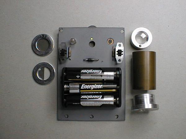
Other optical tests are easily supported by building modified versions of this basic tester. Ross or Dall Null tests may be supported with a tester which carries a lens holder assembly. Figure 3 shows such a lens holder. The parts shown here may be used for Ross Null testing with this test head. The top section is made to attach to the head with screws. (The prototype shown lacks the required mounting holes.) The bottom section is the lens cell which holds the null lens. The center (copper) section is the spacer tube. The carefully measured length of this tube determines the critical separation of the light source and lens when used in null testing.
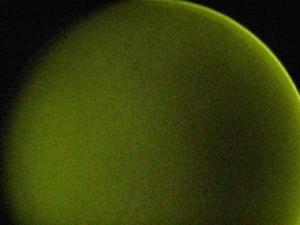
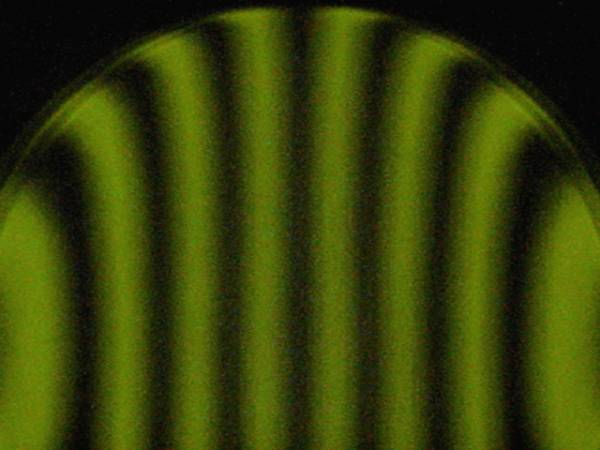
Pairing these test heads with a solid, versatile, carriage assembly creates a very easy to use tester. The low profile design permits the easy attachment of Web cameras or video cameras immediately behind the viewing port. This makes it quite simple to document your progress in mirror figuring. Figures 4 and 5 show views of the Foucault test and Ronchi test for an under-corrected 14 inch mirror. The photographs were taken with an inexpensive Web camera mounted on the tester immediately behind the viewing port. The standard lens of the Web camera has been replaced with an achromatic lens of longer focal length salvaged from the Kelner eyepiece of a pair of old "yard sale" binoculars.
Operation of this tester is just like any other. The first step is to set up your mirror and the tester facing one another. The distance from the face of the mirror to the face of the circuit card should be made equal to the radius of curvature of your mirror. (Remember to use the radius of curvature of the mirror -- twice the focal length for this setup.) Rotate the whole tester as required so that it is squarely facing the mirror. Next you turn on the power to the test card and also turn on the alignment LED. Move the mirror stand around a bit until you see the bright image of the alignment LED on the front of the tester card. (If the alignment was off by a large amount and you cannot find the image on the card, you may want to place a large white poster-board just behind the tester to help pick up the image.) Fine tune the position of the mirror until the image of the alignment LED falls on the center of the alignment port of the test card. Now, turn off the alignment LED.
Final setup of the tester is a little more straightforward when using a Foucault knife edge but can be done with any other test adapters if you wish. Here is how I do my final setup. I move the tester's carriage to within about 1/4" of its innermost travel position. I then look through the test viewing port and adjust the knife edge to cut into the returning beam half way so that its shadow bisects the mirror. I then move the whole tester towards or away from the mirror slightly until the Foucault image shows a pattern that indicates I am very near the center of curvature of the mirror's central zone. At that point, I leave the tester in position and adjust only the carriage travel to its full innermost position. The knife edge should now clearly be inside the center of curvature of the mirror and should cut into the returning beam from the same direction as its physical orientation on the test card. The next step is to adjust the tester's lateral position control so that the knife edge shadow bisects the mirror.
Next, I move the carriage position of the tester to its outermost travel point. When I look at the mirror now, I usually notice that the knife edge no longer bisects the mirror. I adjust the tester's lateral control to bring the knife edge half way back to the bisecting position. Finally, I rotate the whole tester apparatus until the knife edge bisects the mirror. At this point the tester's longitudinal axis should be aligned quite closely with the mirror's optical axis. As a check, you should be able to run the tester's carriage from the outermost limit to the innermost limit and see the knife edge switch sides of the mirror while bisecting it throughout its range of motion. This allows you to move the carriage and watch the donut shadow patterns roll through all the zones on the mirror. If you switch over to a Ronchi test adapter on the test card, you can move the tester longitudinally watching the shadow bands appear and disappear at the sides of the mirror while the center band stays in place. This level of alignment will make all your testing much easier to perform.
Now you are ready to perform the test of your choice. You may refer to the articles on this Web site which describe the actual running of the Foucault Test and the Ronchi Test. Complete plans and parts lists are provided here (for non-commercial use only) so that other amateurs may build this tester design. If you have questions or run into problems, feel free to email me.
Data Files For Modular Tester Design
ZIP Archive Containing All Files Listed Below (80 KB)
Board Patterns Without Copper Fill
Solder Side Board Pattern (14 KB)
Component Side Board Pattern (Optional) (13 KB)
Board Patterns With Copper Fill
Solder Side Board Pattern (24 KB)
Component Side Board Pattern (20 KB)
Drill And Parts Lists
Hole Size Drill List (11 KB)
Parts List (11 KB)